

3D Printed Indexing Gears (MVMT 68) : 7 Steps (with Pictures) - upchurchsucken
Introduction: 3D Printed Indexing Gears (MVMT 68)
This mechanism uses rotary motion to move a gear quickly and on the dot into a fixed position. Using skateboard bearings, you fanny snap these parts together and use the action for all kinds of useful (Beaver State unavailing) machines.
Using gears that have dentition and smooth gaps, you can make a gear twist and stop at just approximately any angle you neediness. This is similar to a geneva gear, simply information technology's much simpler to 3D model and (I think) a little easier to read.
This is the first in a serial of 3D printed mechanisms modeled in Fusion 360 using skateboard bearings and 3D printed parts. The idea is that you'll Be able to use the mechanisms to make all kinds of projects that use mechanical assemblies like robots or any else machine you power lack to make.
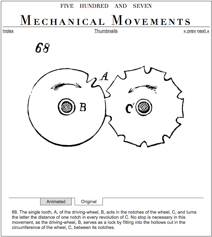
507 Mechanical Movements is an encyclopaedia of common mechanisms from the 1860's that serves as a good reference for this kind of thing. This is going to be along project, so if you've got a specific mechanism you'd equal me to make, feel free to make a quest in the comments!
Oh, and what's it smashing for? You can add a couple of parts and frivol away pingpong balls all over the floor!
Step 1: Tools and Materials
- Fusion 360
- 3D Printer
-
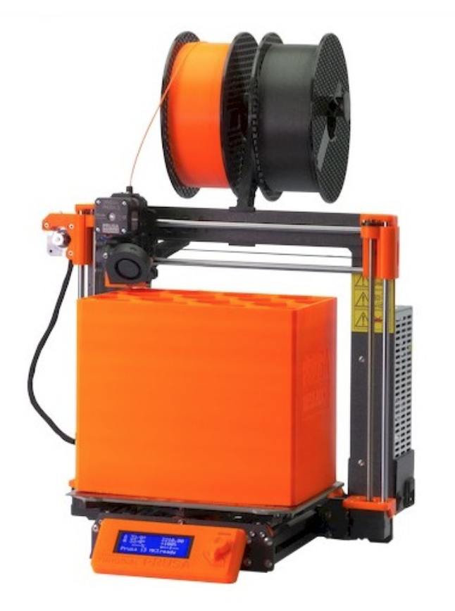
I use a Prusa I3Mk3S for only about everything. Information technology's the best bon for your long horse, in my opinion- real well ready-made, 3D printable replacement parts, accurate and reliable.
-
- 3D Print Filament
- I used Matte Character HTPLA from Early-pasta for this project, but pretty much any filament will work. I like this stuff because the finish looks in truth satisfactory.
- 608ZZ Skateboard Bearings: There are heaps of types to choose from, but any cheap ones leave do. Don't worry too much about "spin time" as you would with restlessness spinner.
- M3 Screws + Nuts: You could practice any screws and buggy around this size, but I find these work asymptomatic for small 3D written mechanical projects.
Unification 360 is free and it's awesome. I use it for everything I design and fabricate.
Student / Educator License (renew free every 3 long time)
Hobbyist / Startup (regenerate non-slave yearly)
Follow along with this Instructable to fashion mode your own!
Step 2: 3D Files
The STL files are ready to lading into your slicer to make exactly what you experience in the model. The .f3d file away is a Fusion 360 archive that you can upload to your own Optical fusion plan.
Here's a link to the public Fusion 360 simulation if you want to avoid downloading and uploading, you can open it and save it as a new filing cabinet: hypertext transfer protocol://a360.co/2f1gYQ5
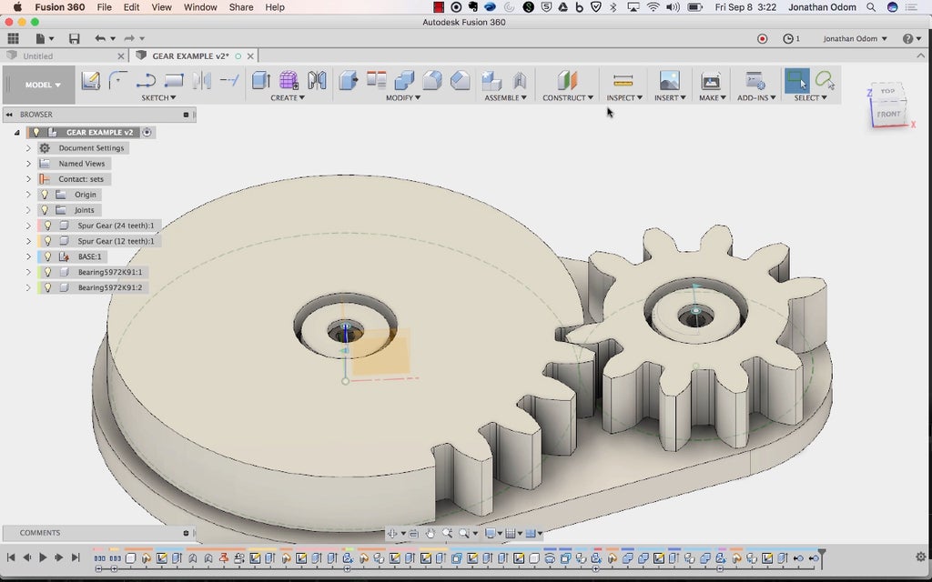
Maltreat 3: Making Spurring Gears in Fusion
This mechanism is based on a standard spur track gear. All you need to Doctor of Osteopathy is stimulate some interfacing spur gears, then cut out some of the dentition to create the indexing accomplish.
Fusion comes with a plugin that makes it impressionable to create spur gears. In this footstep I'll go finished the sue and explain some of the terminology.
Caveat: I'm not an locomotive engineer, I'm generalist designer who understands the complexities of topics suchlike this with clean enough depth to clear what I want to make. Thither are many Former Armed Forces more surefooted people than Pine Tree State on Instructables, hopefully more or less of them volition barge in and straight Pine Tree State in the believable even that I get something wrongfulness.
Spur Gear Add-In
To make a spur track gear, go to ADD-INS > Scripts & Bring-Ins, then select SpurGear from the list. You'll bring a popup window where you fundament enter parameters. This is what they mean, more or less:
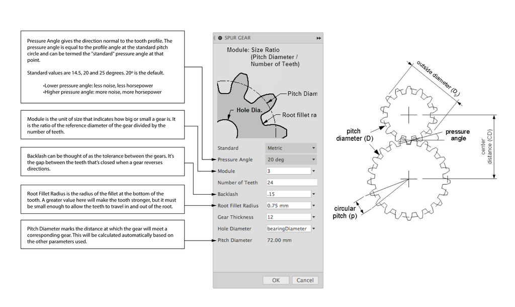
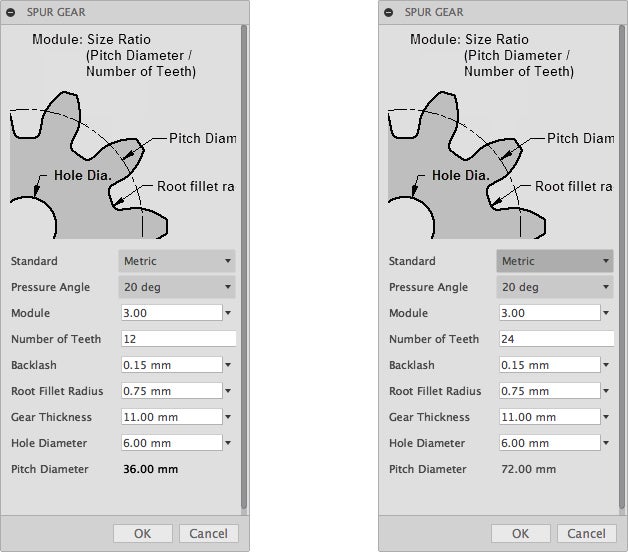
I'm going to make a 2:1 gear mechanism ratio with the large gear beingness the driver. That way that the smaller gear will have 2 rotations to every 1 gyration of the larger gear. The little gear wish rotate twice American Samoa immoral. Watch the video above if you want to have a go at it more about what the parameters mean.
If you wishing to design your own gears, here's a great resource:geargenerator.comWith this browser tool, you can quickly design gear assemblies, see how they move, then copy and library paste the info into Coalition to make 3d-printable gears.
The placement of the gears is simple. Just move one of them by the union of the Pitch Radius (pitch diameter /2)of both gears. In this case, that's the (36/2)+(72/2) = 54mm. You'll know the spatial arrangement is set because the green dashed cartoon lines should beryllium affecting apiece some other when viewed from the top.
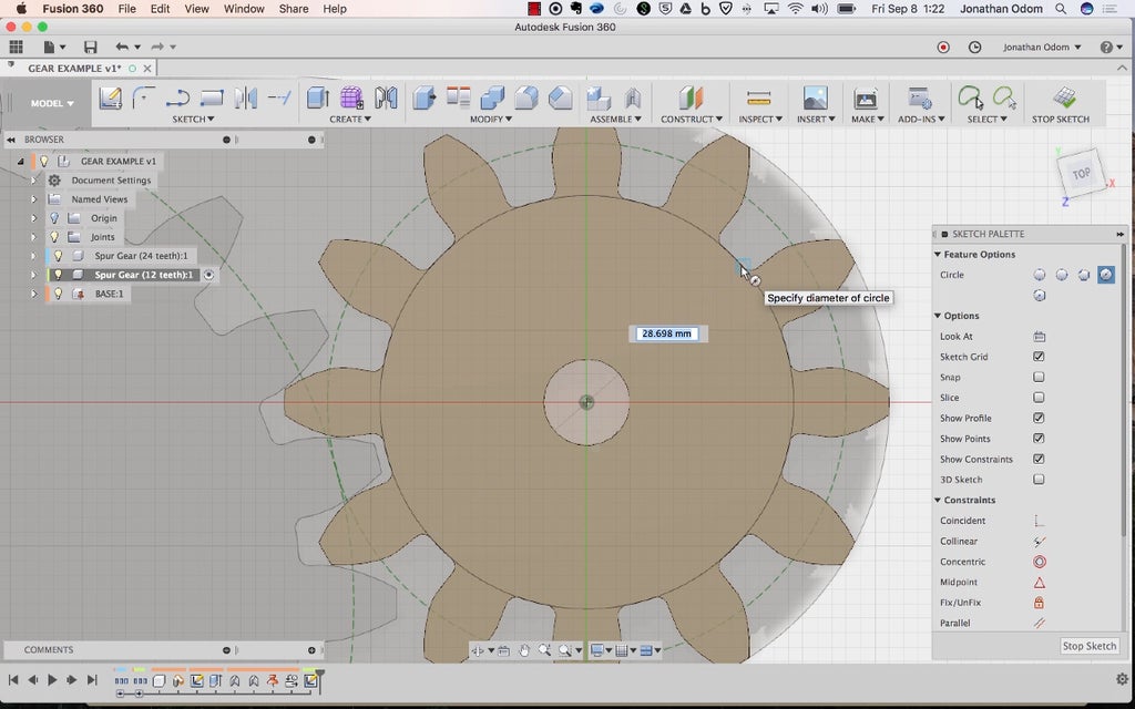
The gears wish be created in the same location with the said rotation, so to make them network correctly, just circumvolve one of the gears by a value of 360º/(Number of Teeth / 2). In this suit, I rotated the 12-tooth cogwheel by 15º.
Step 4: Turn Spur Gears Into Indexing Gears
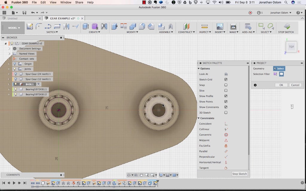
With the gears in situ, you'll have to cut out or s of the teeth to get the indexing effect. I'm going to make the smaller gear bash the indexing, soh I draw a Sketch circle snapped to the gear's root.
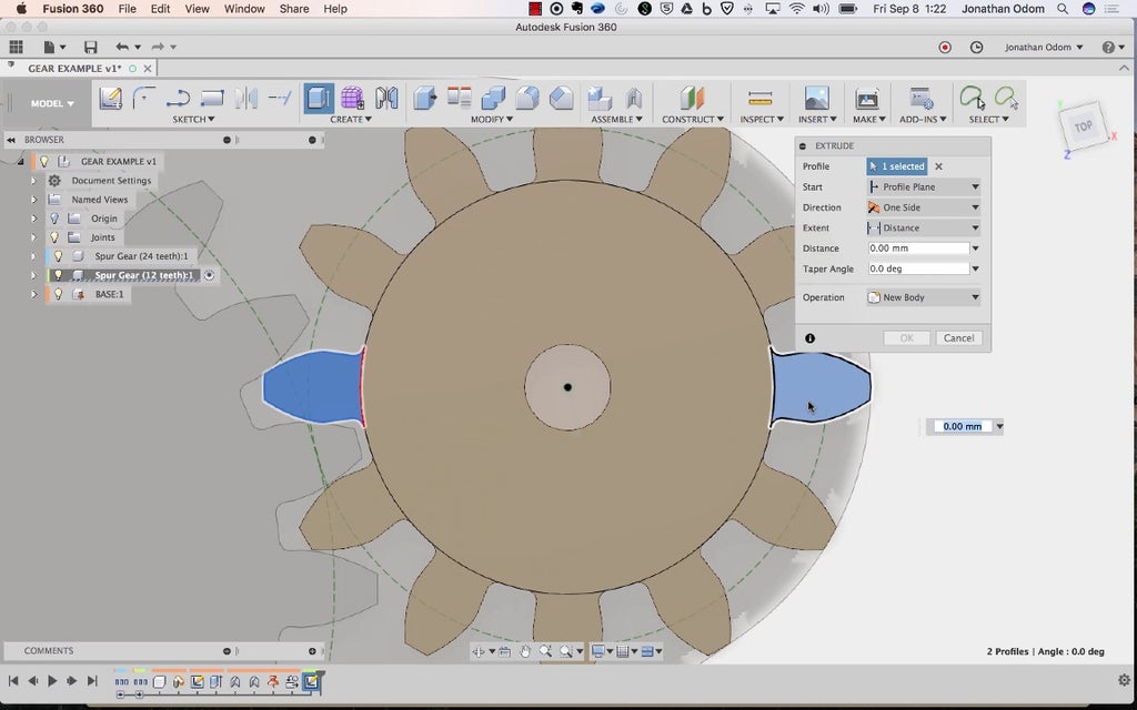
I need this cogwheel to indicator at 180º, so I'm going to move out two of the dentition 180º from each different (on opposition sides as shown).
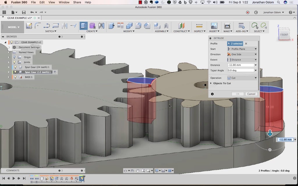
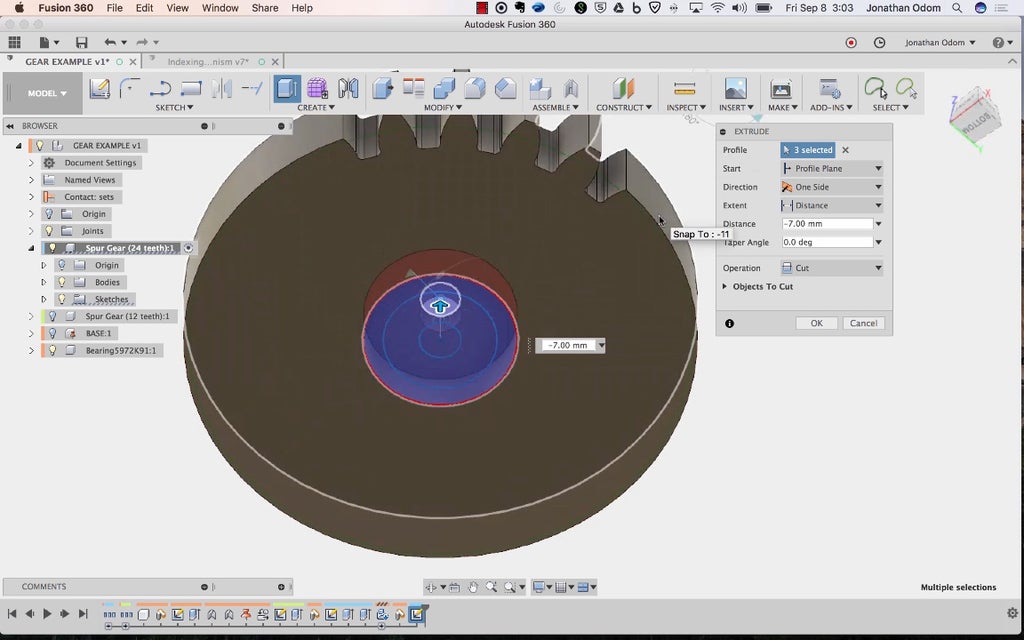
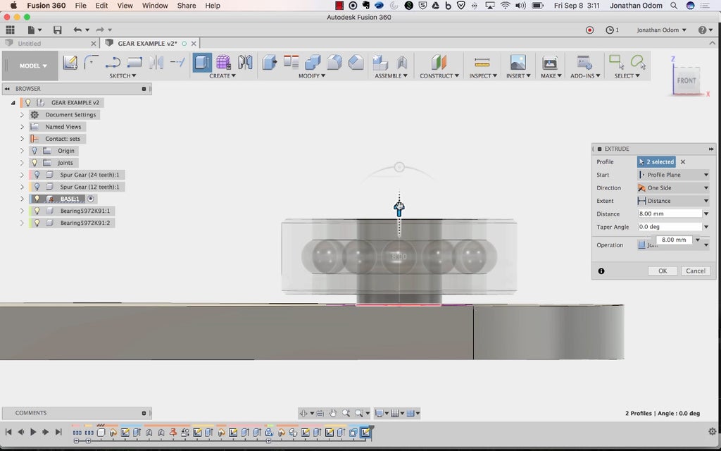
Victimisation Make over > Squeeze out, I prize these two profiles and cut all the way to the base.
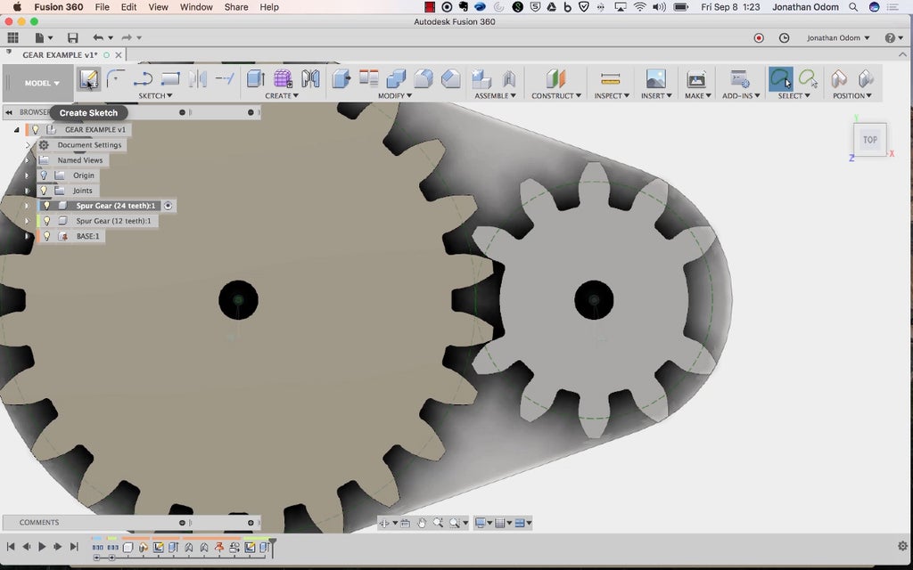
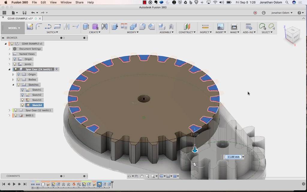
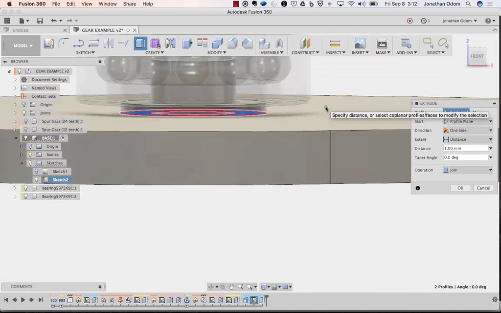
Now I'll need to alter the larger gear. I create a sketch on its go past face.
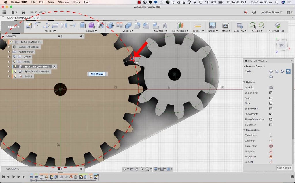
The circle you'll need on this gear mechanism is going to make over a surface for the littler gear to bear on while the large one turns. This circle has to snapshot to the recess of one of the dentition on the sides of the gap as shown in the screenshot (you'll ensure why below).
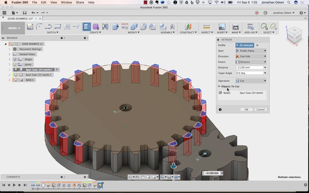
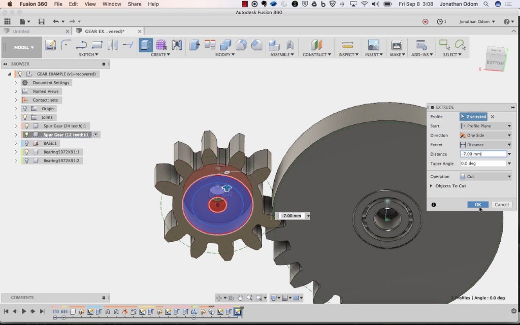
Using the new profiles made by the circle, I Extrude to cut the ends of the dentition that we won't be using. Since each of the tooth sections on the small power train has 5 teeth, we need 5 roots and 4 dentition on the larger train.
With those teeth cut out, I use the other profiles to fill in the gaps using Extrude with the Union operation.
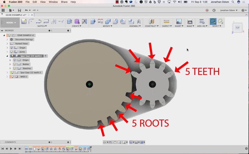
If we've got 5 teeth and 5 roots, we should get a 180º indexing movement on the small gear with all rotation of the large gear.
The arrow in the GIF above shows how the pitch moves!
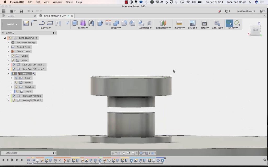
Stone's throw 5: Integrate Bearings and Hardware
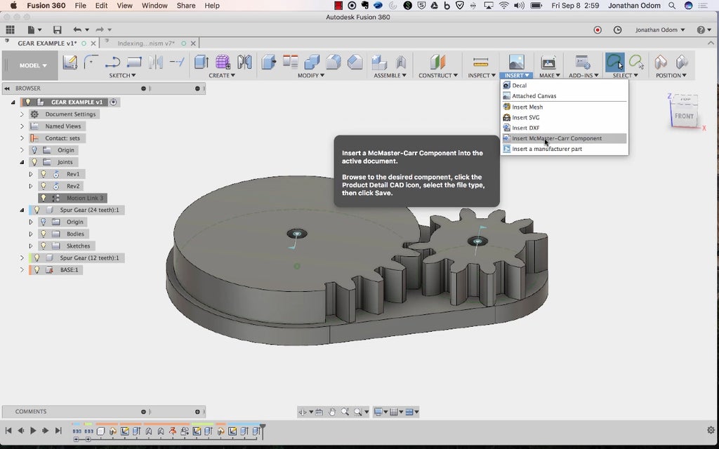
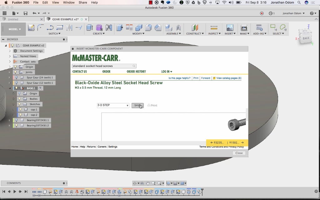
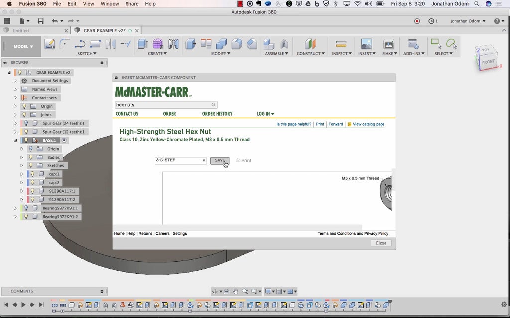
Right away that the gears are fit, it's time to bring in the bearings and add some new features. I attend Insert > Insert McMaster Carr Part to find a aim model.
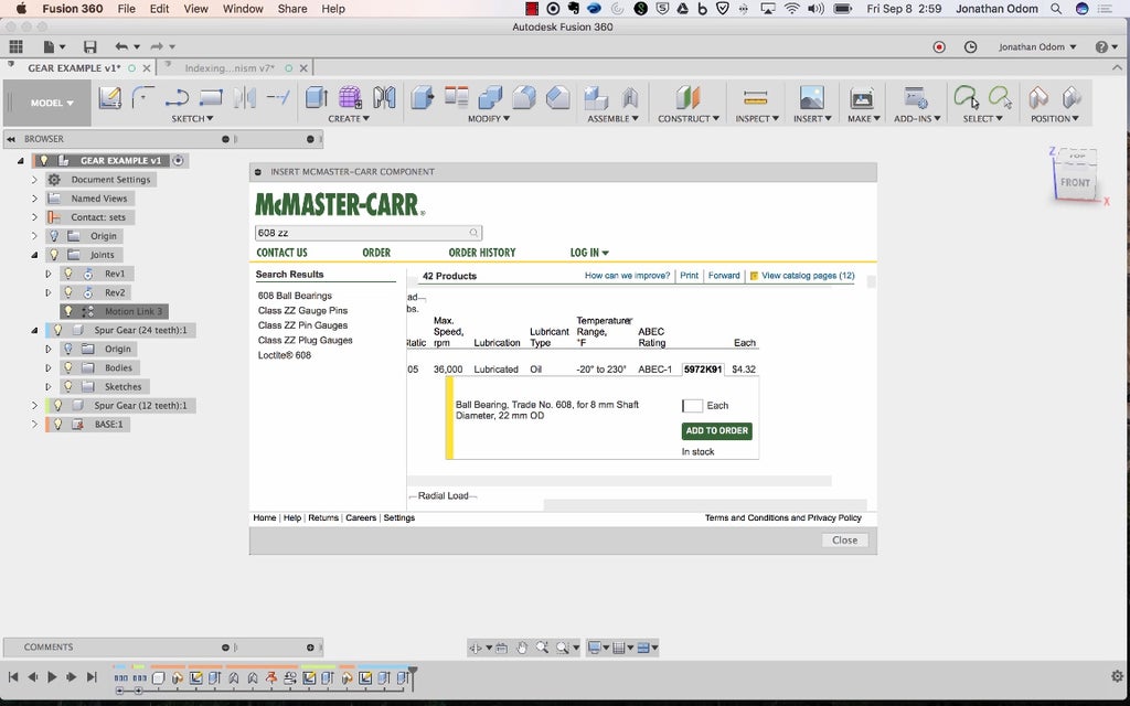
Searching 608ZZ (a standard skateboard bearing you can retrieve roughly anywhere), I pick up the premiere one I find.
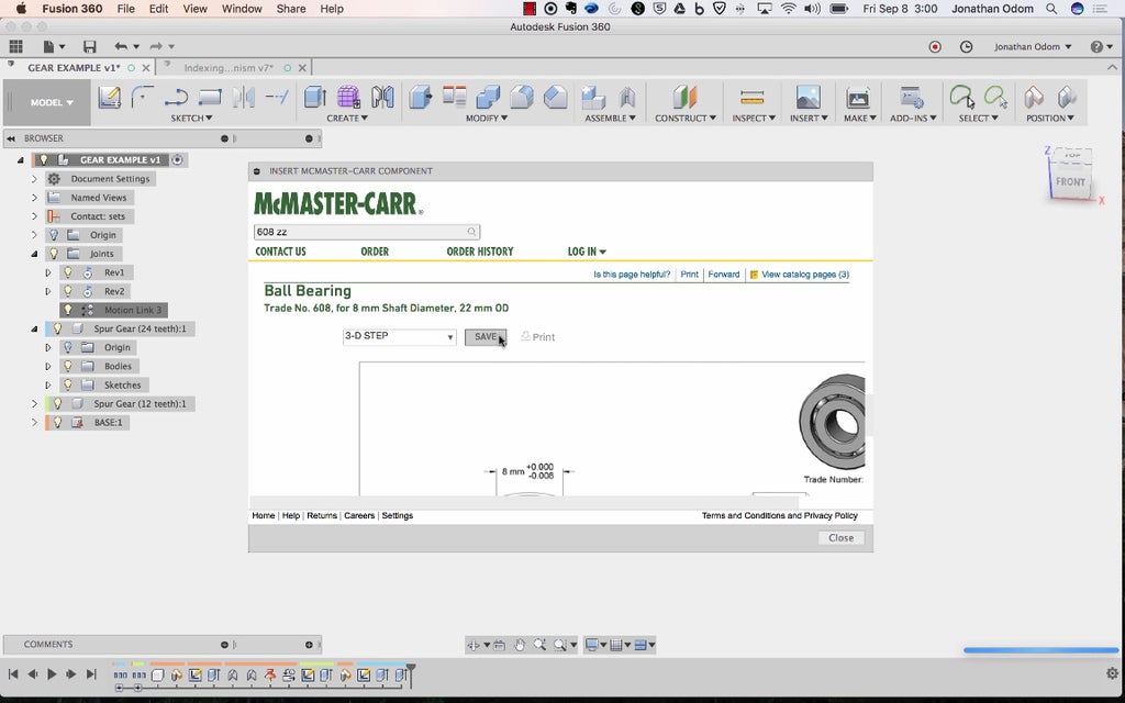
With the file typecast set to 3-D STEP, I chatter SAVE and the model comes in as a component.
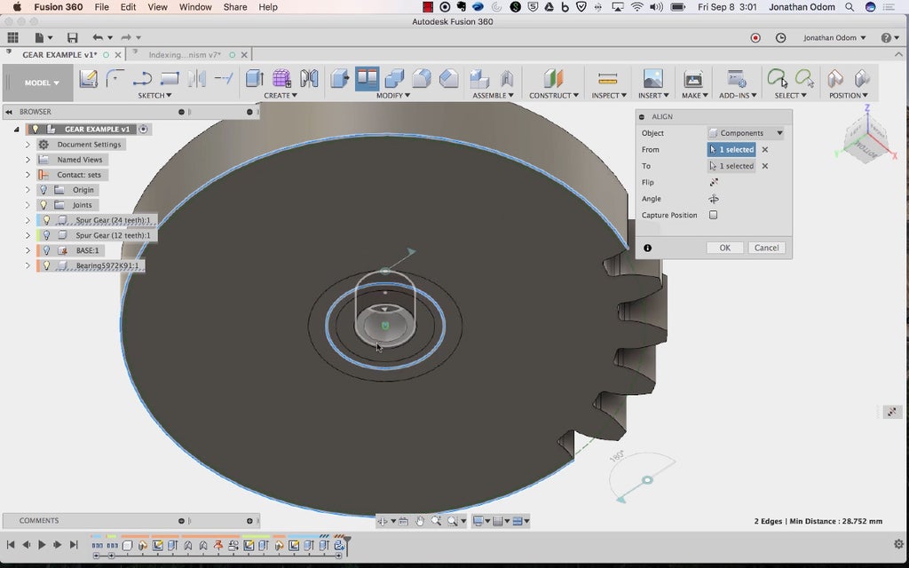
I move the bearing thus that information technology's aligned to the center / arse face off of one of the gears.
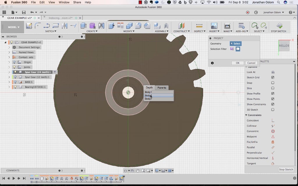
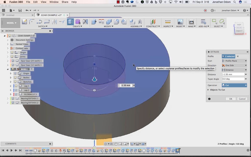
I make a Sketch on the bottom of the gear, then Sketch > Project / Include > Project with Bodies in the Selection Separate out, then click along the outer ring of the bearing. This gives me the circular perimeter of the bearing.
I use Make > Squeeze out to pierced out a cylindrical shape that's the same height as the posture, giving me a cavity in the pitch. Watch the video above for more inside information happening this ill-trea.
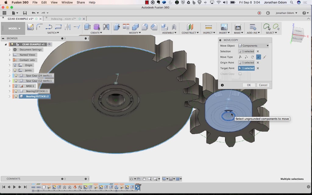
I copy the bearing over using point-to-point in the Move / Copy panel. This makes it easy to get the bearing in exactly the right place.
I reprise the Sketch - Project - Extrude steps I used for the other gear wheel, once once again devising sure I'm solely cutting done the gear by concealing the bearing in the Browser.
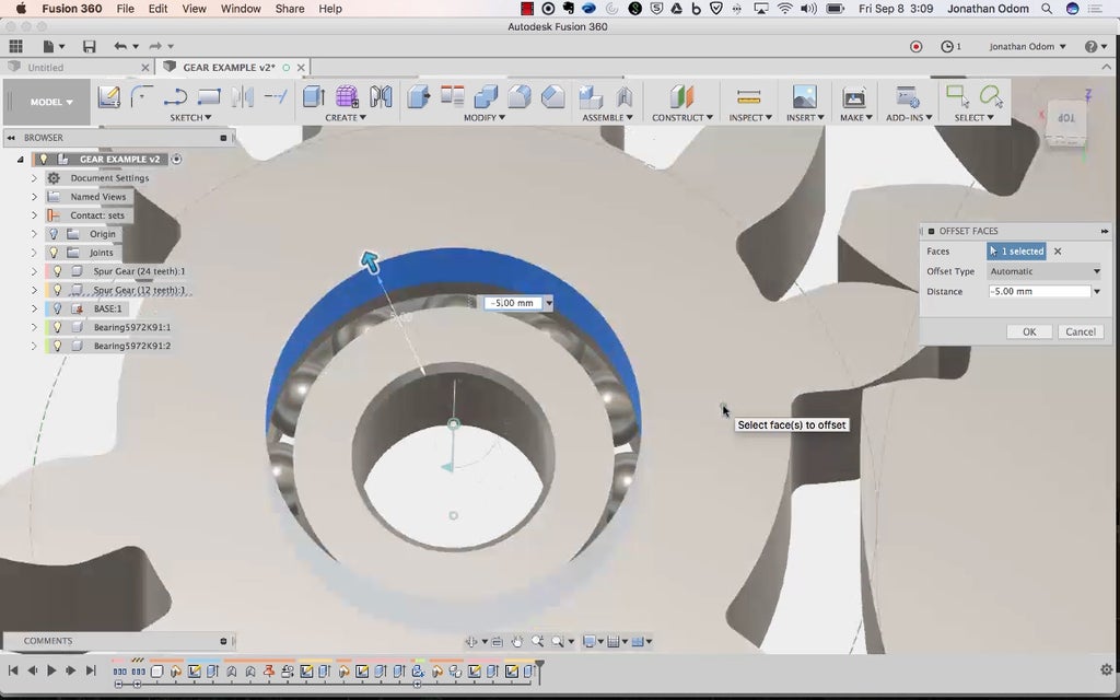
To see that the bearing rings move freely, I use Press/Pull to make the holes in the gears larger than the inner doughnut of the bearing.
Now I deman to add attachment features along the base of operations. I create a Sketch on the uppermost, and then Cast the inner rings of all bearing.
I Extrude the inner profile to just concluded half fashio through the carriage.
I past make a chopine from the same sketch for the inner ring of the bearing to rest on. This will give the gear plenty of clearance to spin freely.
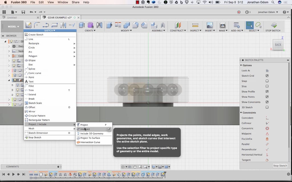
Now I need to cook caps to harbor down the bearings. I create a sketch in the side plane, which is coincident with both of the gear axes. I go to Sketch > Project / Let in > Cross.
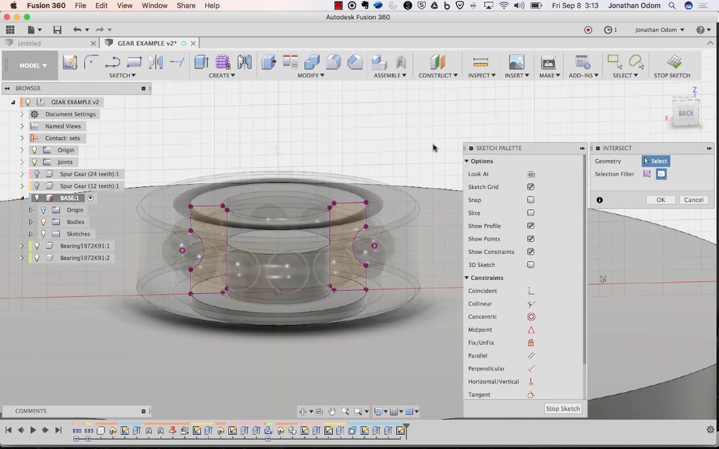
With Selection Filter plant to Bodies, I snap on the inner doughnut of the bearing. This gives me a profile I can use to ensure that my cap fits properly inside the comportment.
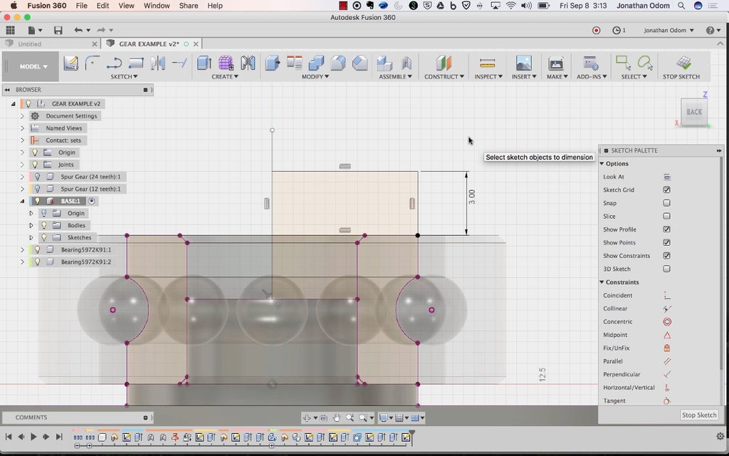
I draw half of the face profile of the cap, because I'm going to use the Revolve command to make the cap.
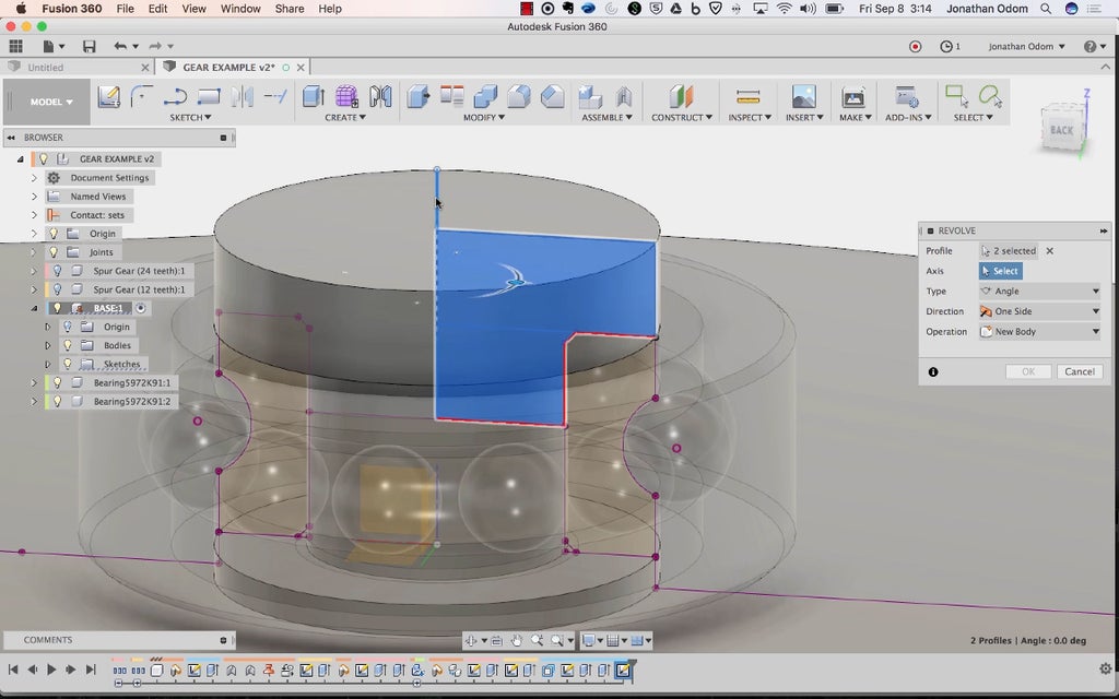
I attend Create > Revolve and select the Formed profile I just made. The Axis is the centerline of the profile I drew. This should feed me a mushroom molded cap.
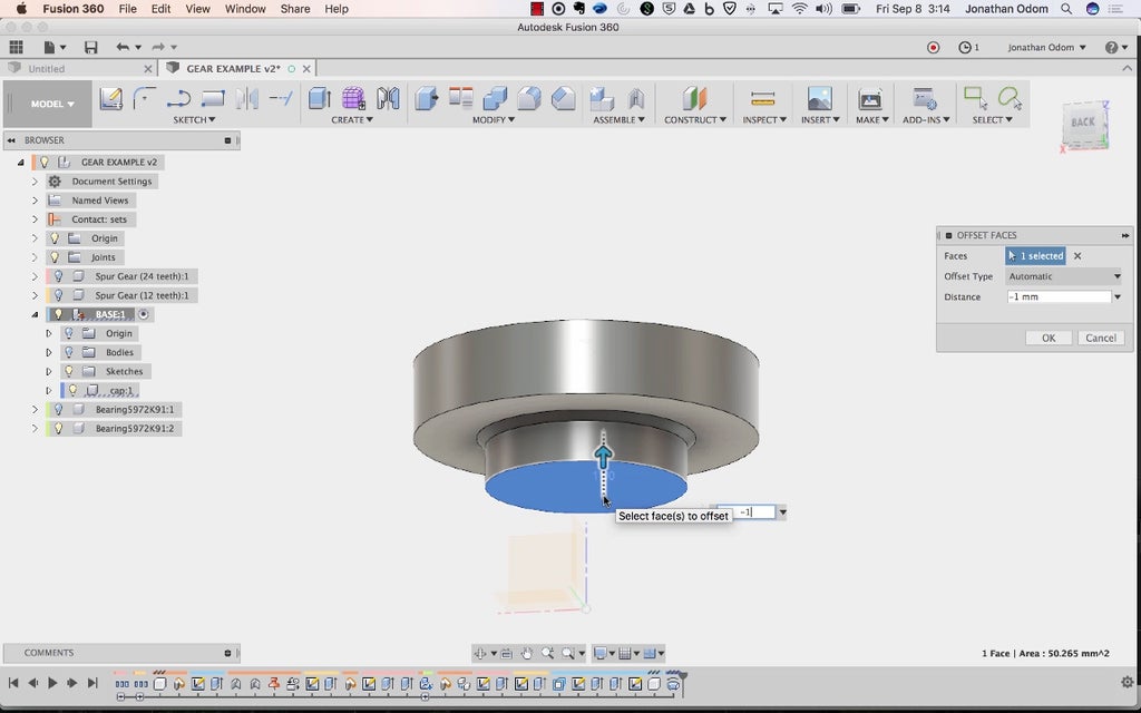
I employ Pressur / Pull to give myself whatever space betwixt the end of the detonator and the top of the post below.
This gap will ensure that the screw and nut volition be able to put enough pressure happening this assembly.
Next, I'll indigence an M3 X 25mm socket cap machine gaoler. I know I need a 25mm screw because I measured the distance from the top of the cap to the bottom of the base. I repeat the McMaster Carr steps I used for the bearing, this time searching for a screw that fits the bill.
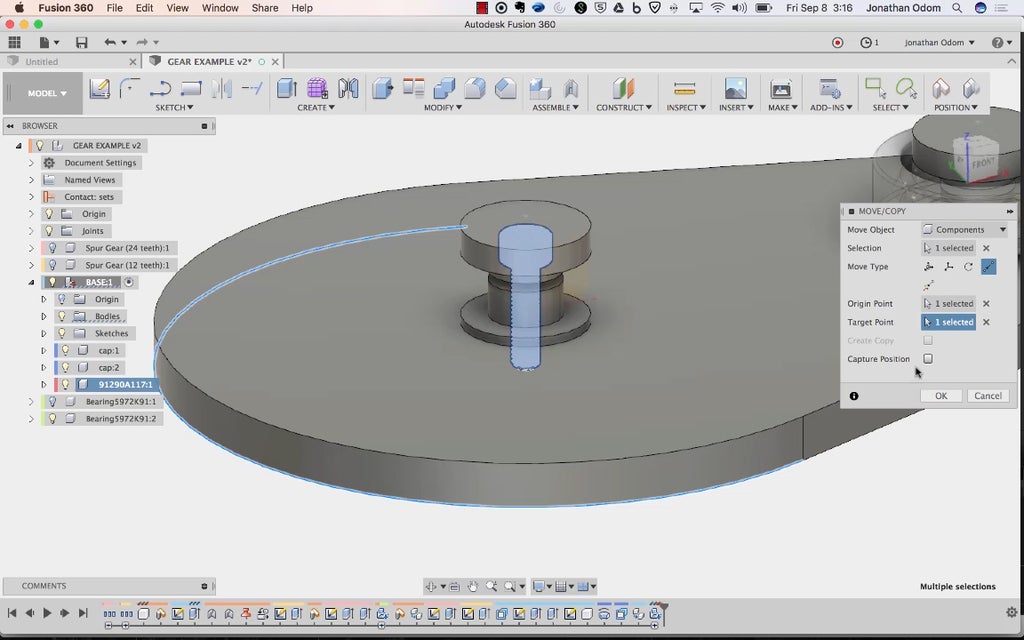
I align the screw so that it's centered on the axis of the bearing. This can Be through with the align tool or point-to-point be active.
I make a study on top of the cap, plan the visibility of the screw from that view, then Squeeze out that visibility to the posterior of the eff cap. Make fated you're non cutting through the screw overly!
I go back to McMaster-Carr and bring in an M3 nut.
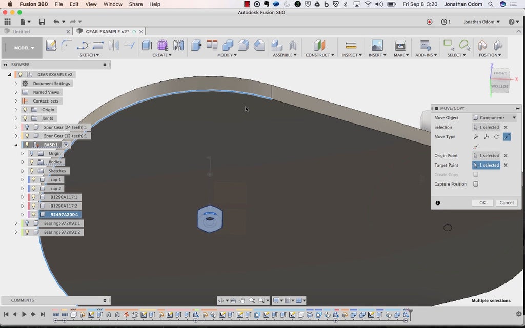
The nut besides needs to comprise aligned to the bottom face of the base, centered happening the screw. I copy the en over to the other side to line astir thereupon screw and bearing.
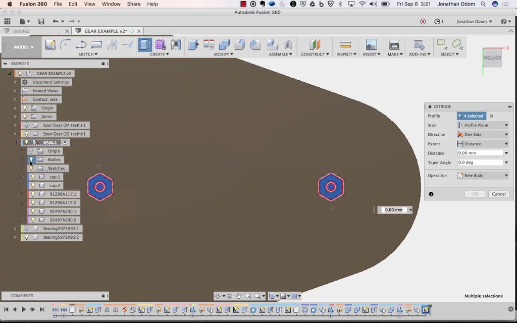
I create a Sketch and jut out the profiles of both of the nut bodies.
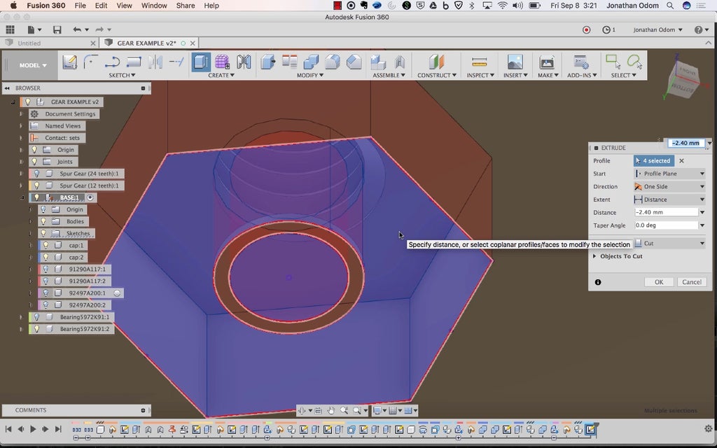
I use these profiles to Extrude and cut out the cavities, orientating the heights with the first-rate of the nuts.
This will give you a working bag model that you can use to nominate any number of contrastive gadgets.
Step 6: Fabrication
So what's this mechanics good for? Well, lots of things. It's generally used in manufacturing- imagine a prise moving widgets onto an production line with equal spacing. It's used to switch tools on a CNC machine arsenic well. I decided to use mine to shoot pingpong balls out of a tube in rapid succession!
If you open the Unification 360 file, the whole assembly is there for your reference, and the STL files (step 3) are cook to publish.
I added some features that silken out the edges and attain parts easier to assemble. If you're curious in this part of the cognitive operation, ping me in the comments and I'll offer my advice on how to push your work forward.
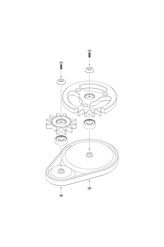
Basic, the bearings are placed on the posts on the base. The screws and nuts living the bearings in piazza and the gears press fit onto the bearings.
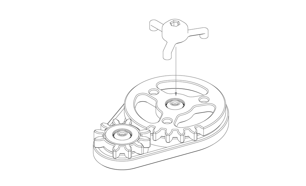
I ready-made holes in the tops of the gears- 3 holes at 120º on the driver gear wheel and a circular groove on the indexing paraphernalia. A little detonating device with a hexagonal hole on top push fits into the holes connected top of the driver gear.
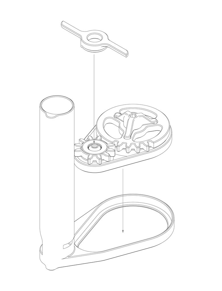
I designed a trigger mechanism to snap into the indexing gear, and a tube that fits 6 pingpong balls with a slot in the side.
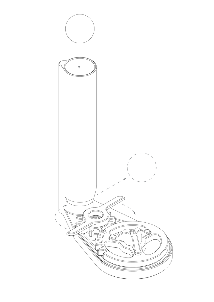
When the driver gear spins counter clockwise, the trigger swipes direct the opening and knocks the balls tabu.
Footfall 7: Launch Some Pingpong Balls!
Here it is in litigate! What would you use this mechanism for? Post an IMadeIt below and I'll give you a free one-year premium rank.
Be the First to Share
Recommendations
Source: https://www.instructables.com/3D-Printed-Indexing-Gears/
Posted by: upchurchsucken.blogspot.com
0 Response to "3D Printed Indexing Gears (MVMT 68) : 7 Steps (with Pictures) - upchurchsucken"
Post a Comment